Hall dimensions
Adjust the width, length and height to suit the site and intended operation.
The starting model helps compare the hall volume, three large industrial doors and longitudinal operation. The dimensions must always be based on the specific equipment or aircraft.
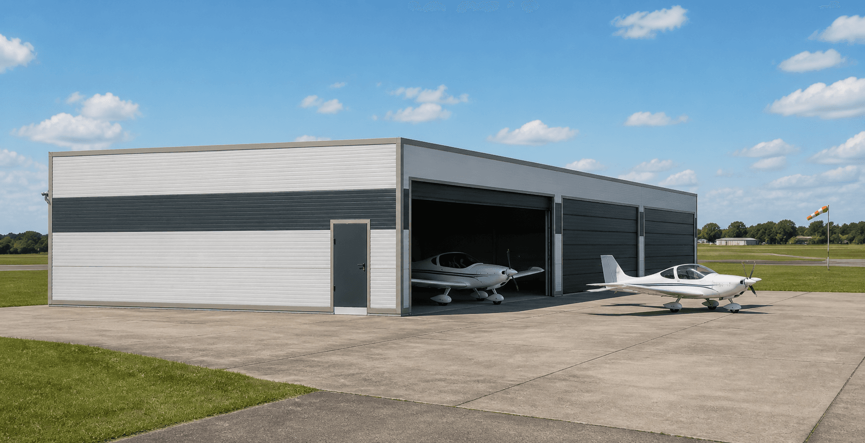
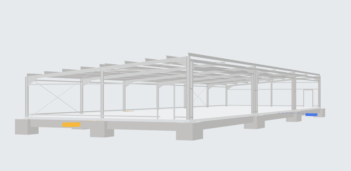
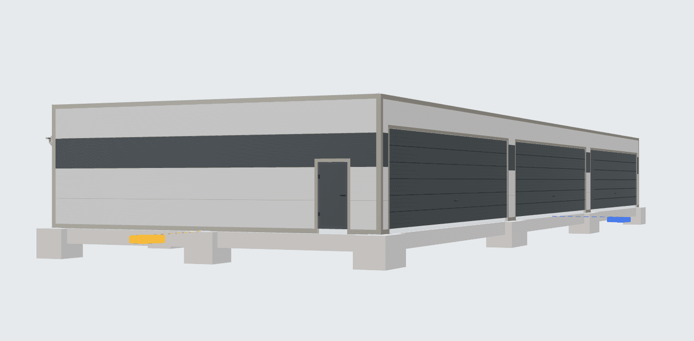
The model shows a long mono-pitch hall with three large sectional overhead doors.
The details describe this starting model. It is a preliminary study, not structural design, fabrication or construction documentation.
It is not enough to check whether the machine or aircraft fits inside. You also need safe access, industrial door operation, maintenance space and room around the building.
What are the maximum equipment dimensions, including wings or working parts?
What clear opening and safety margin must the industrial doors provide?
How much space is needed in front of the hall for alignment and turning?
Where will maintenance, storage, charging or other technical facilities be located?
The Studio opens the 12 × 36 m model with three large industrial doors, which you can edit together with the envelope.
The description is based on the issued template and verified model documentation. Detailed technical assessment belongs to the relevant specialists.
The load-bearing structure consists of seven transverse steel frames at six-metre centres. The 432 m² open internal space is ready for aircraft, large machinery and associated operational facilities.
The 5° mono-pitch roof consists of 120 mm insulated sandwich panels in RAL 9006, while the wall cladding consists of 100 mm panels in the same colour with a RAL 7016 stripe. The design includes three 11 × 3 m sectional overhead doors and two solid personnel doors. This is a study; the final member sizes, foundations, anchorage and fire-safety design will be determined by the subsequent specialist design. The third image is an AI-generated product visualisation, not a photograph of a completed building.
The model does not define airport rules, fire-fighting equipment, flooring, load capacity or service technology.
The previews help you understand the geometry and scope of the study before opening the model in the Studio.
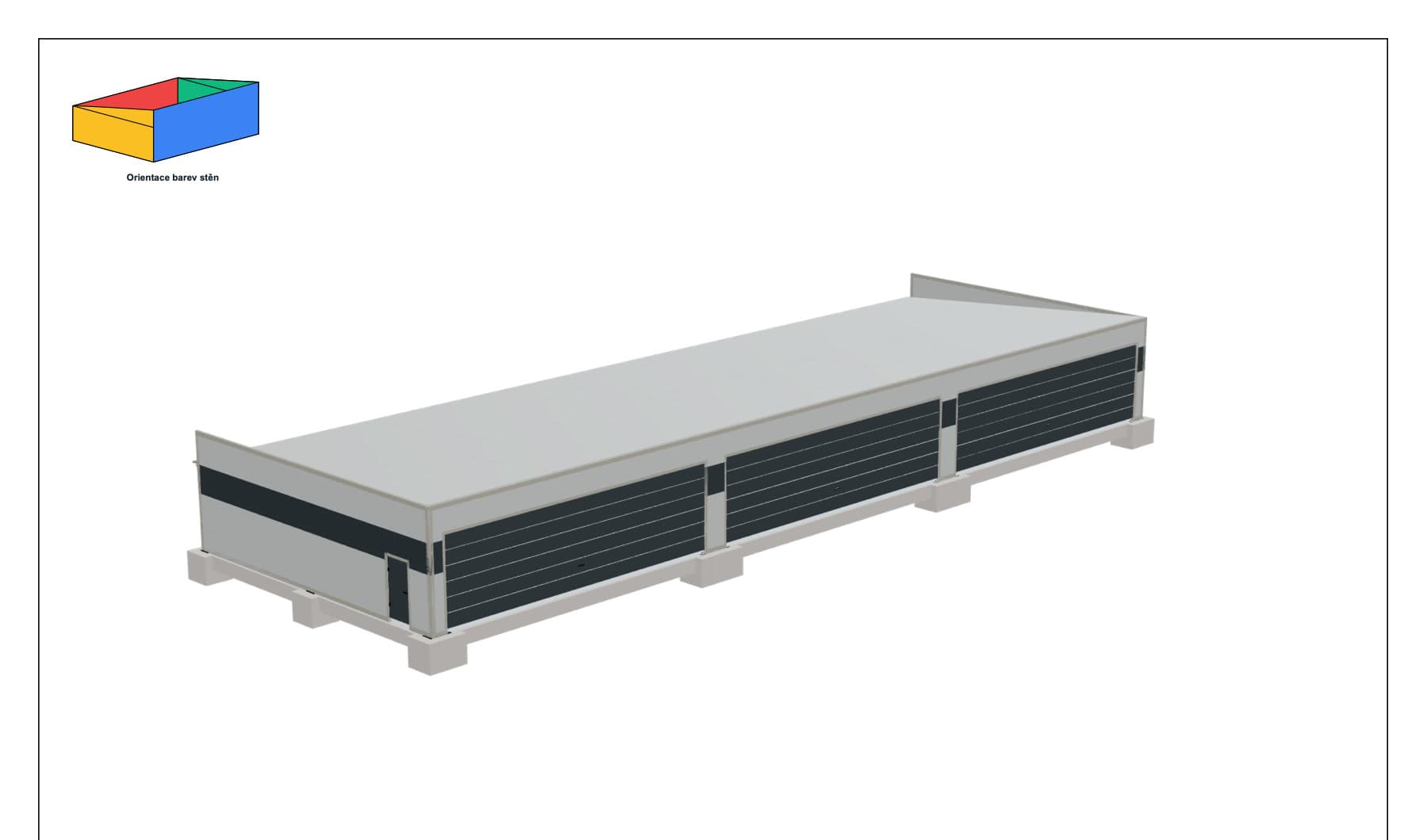
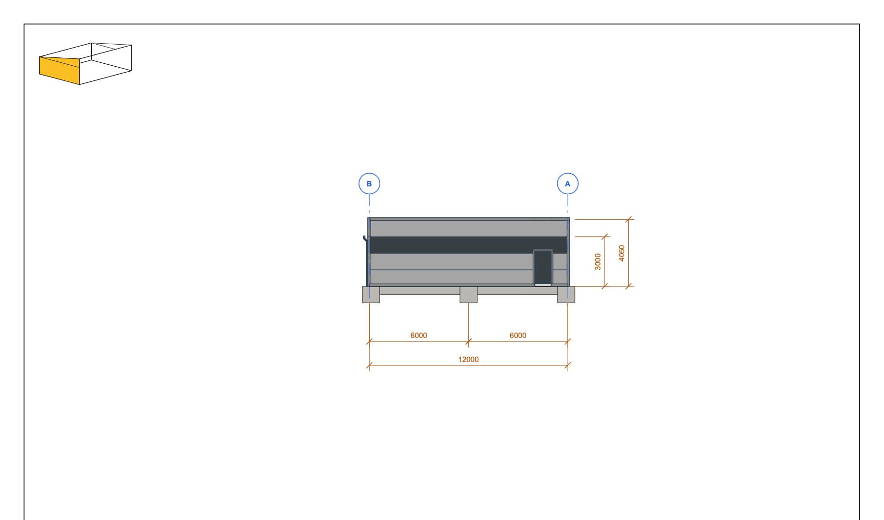
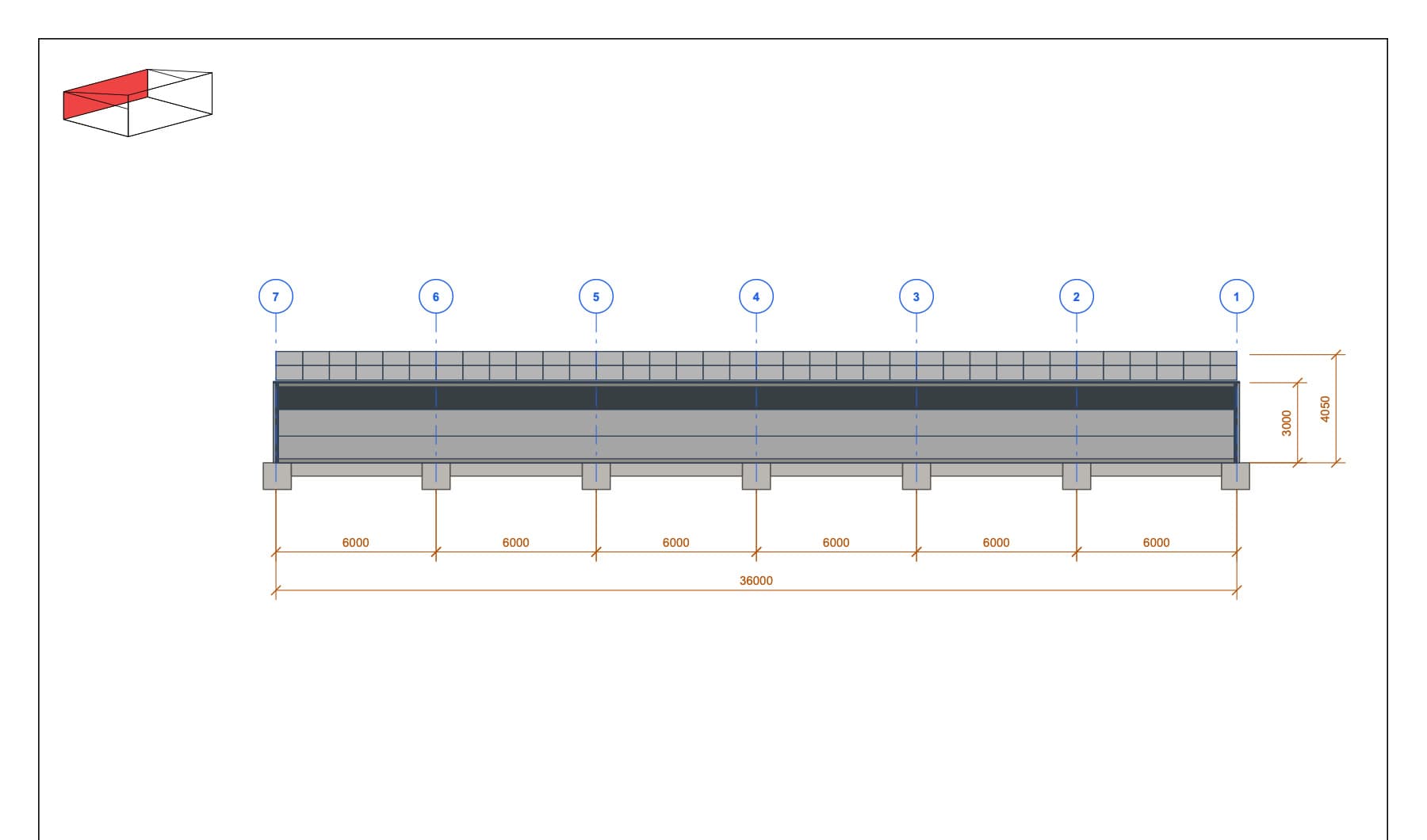
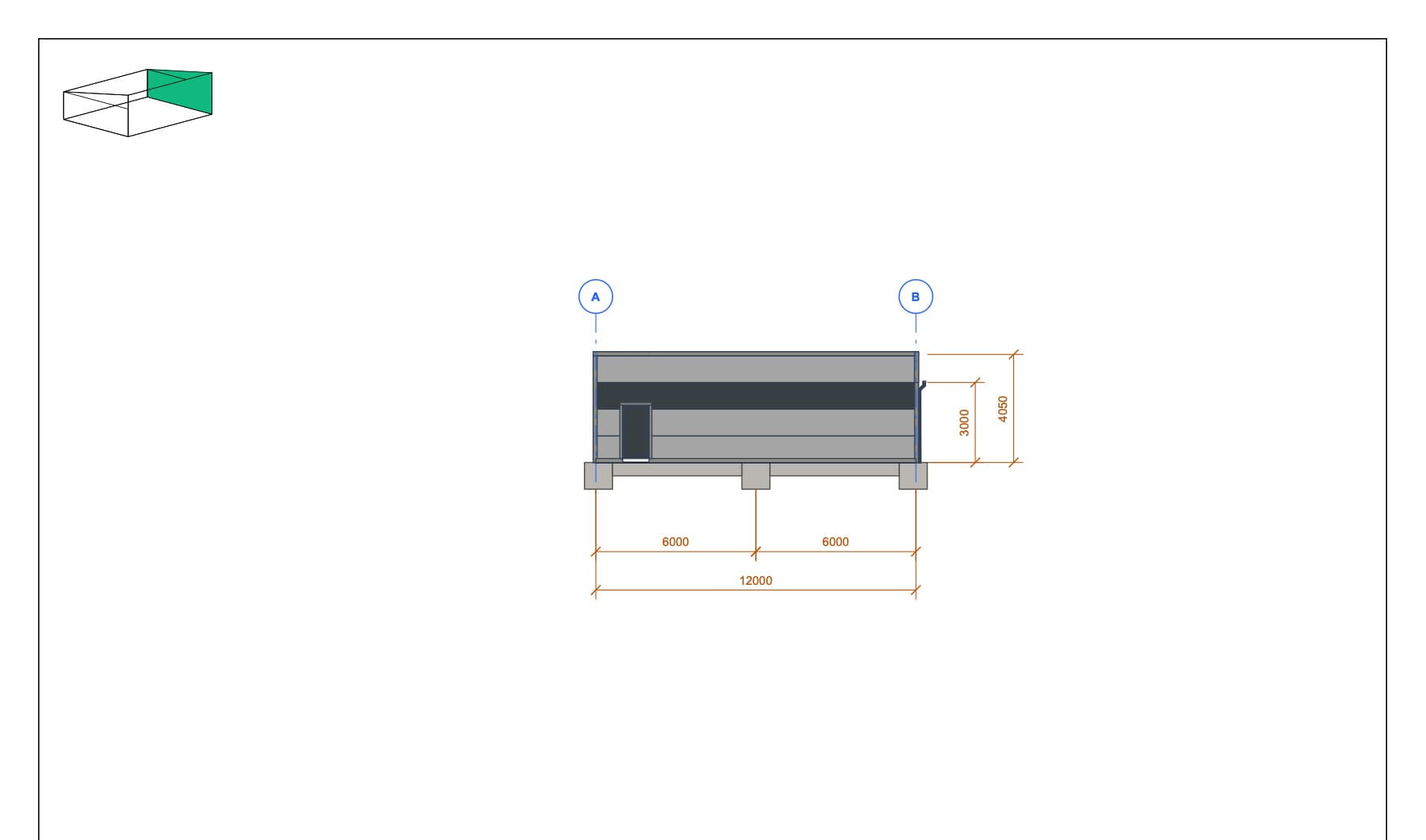
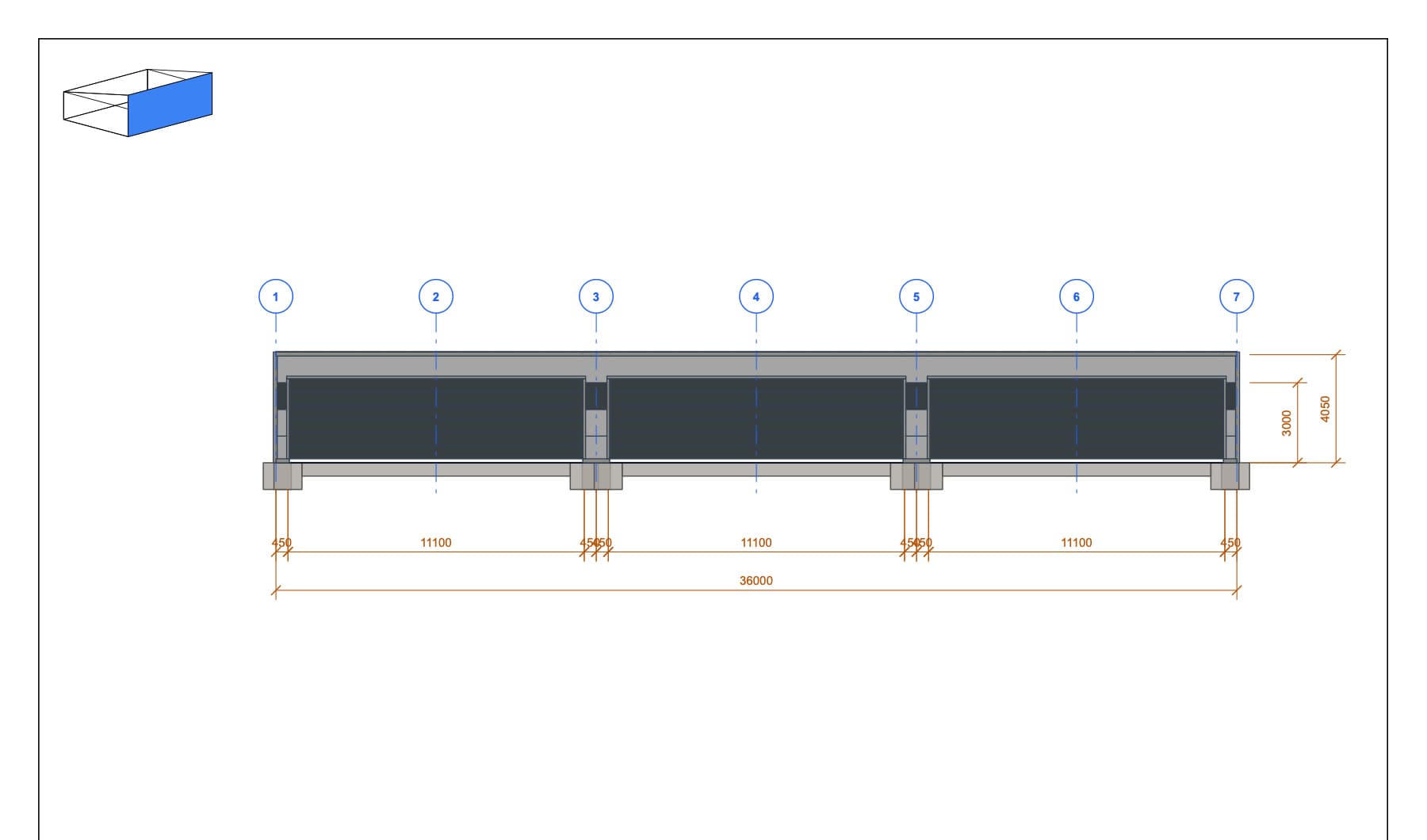
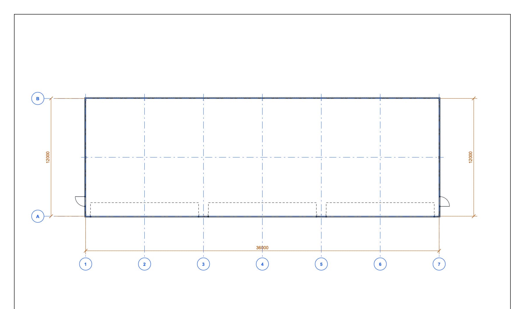
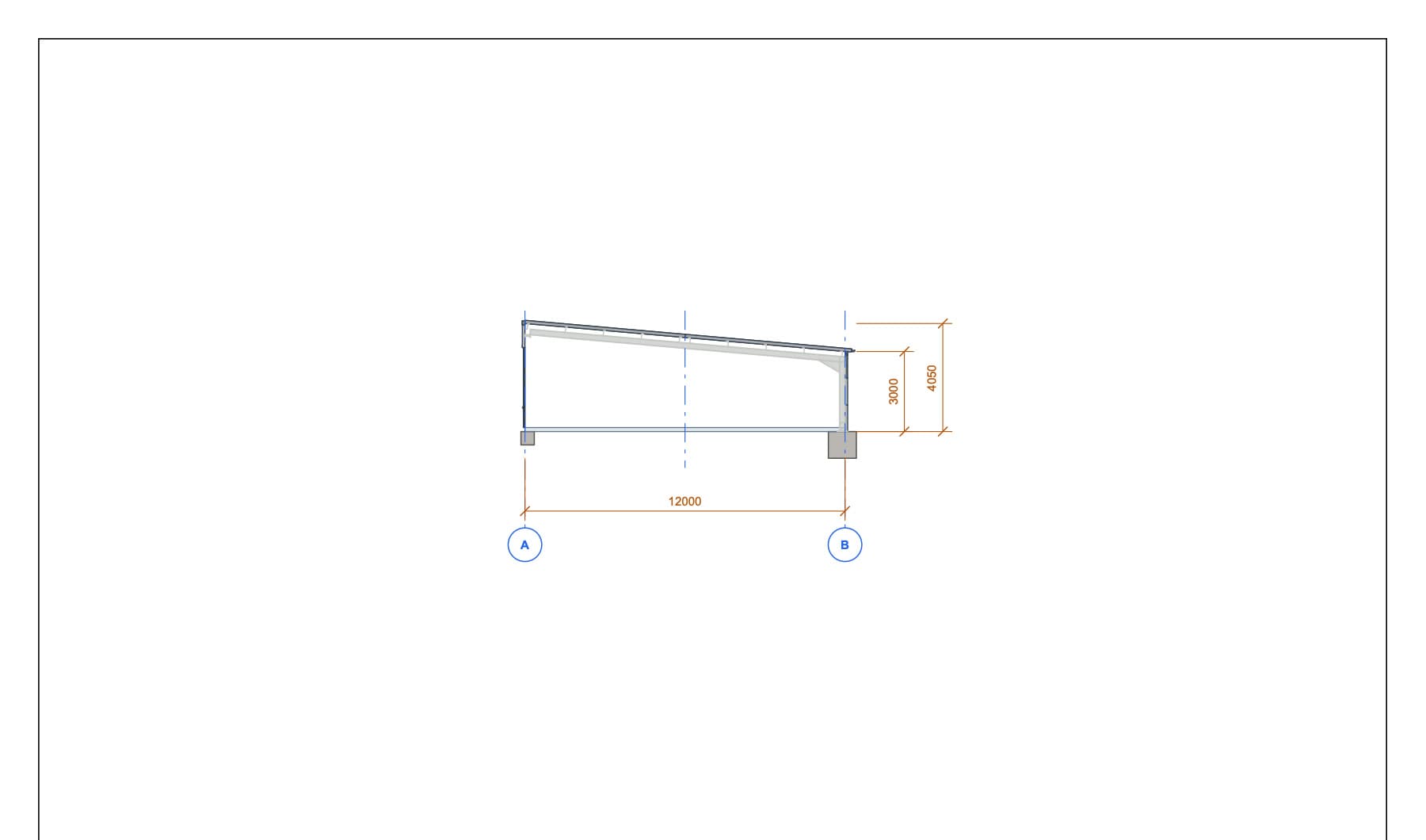
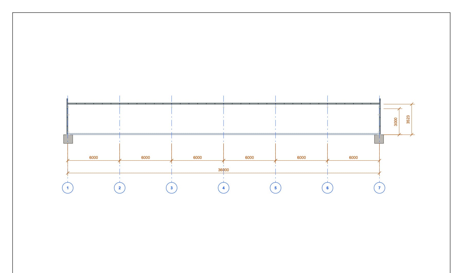
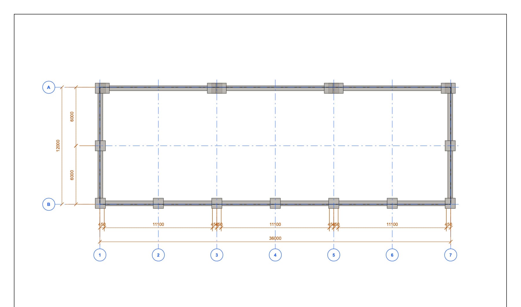
These compact previews show the structure of each file. The labels describe what each document contains.
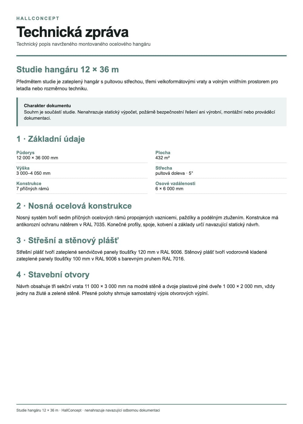 Technical report
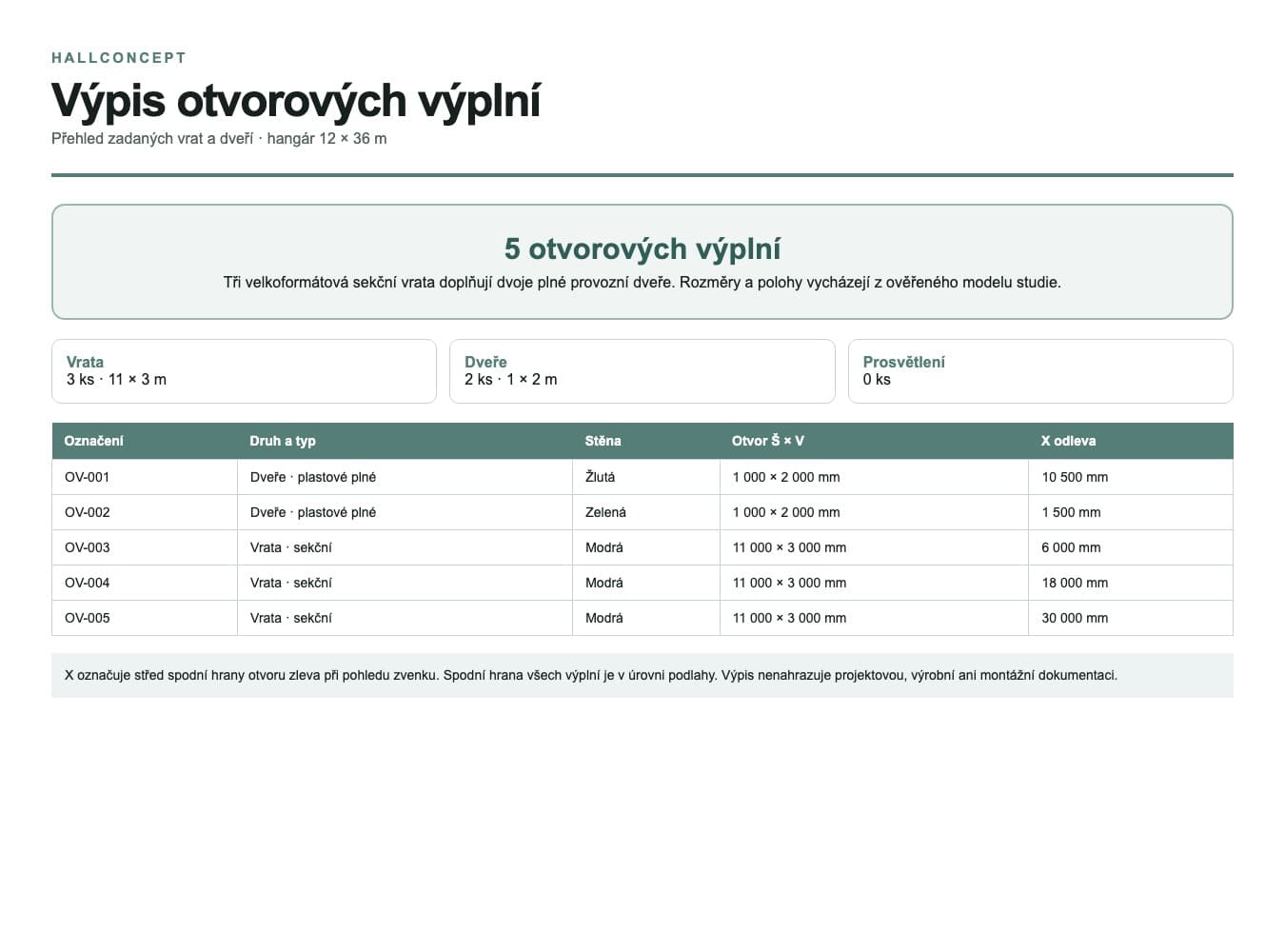 Schedule of openings
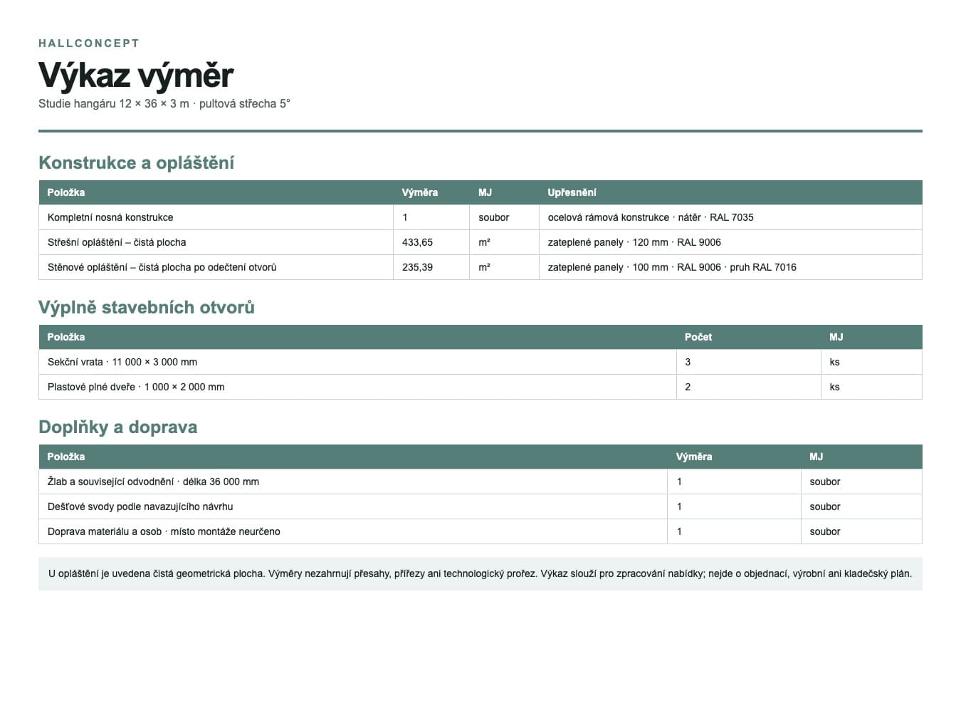 Schedule of quantities
Check every change to the dimensions and industrial doors against the actual equipment outlines and handling routes.
Adjust the width, length and height to suit the site and intended operation.
Compare a suitable roof shape and its basic geometry.
Position openings according to the movement of people, vehicles and materials, and the need for daylight.
Try different material and colour solutions for the external and roof cladding.
Answers about industrial doors, space and the scope of the model.
Yes. You can adjust the openings in the Studio. The final selected industrial door system, lintel structure and loads must be checked by the designer and industrial door supplier.
No. The basic volume can also be adapted to other large equipment. The decisive factors are the actual dimensions and operational requirements.
No. The floor build-up and load capacity are designed according to the specific equipment, loads and ground conditions.
Open the model and compare the hall volume, industrial doors and access requirements.
Open this model in the Studio