Hall dimensions
Adjust the width, length and height to suit the site and intended operation.
The model shows one possible form of an extension but does not define the actual structural connection. First check the existing building, operation during construction and fire-safety implications.
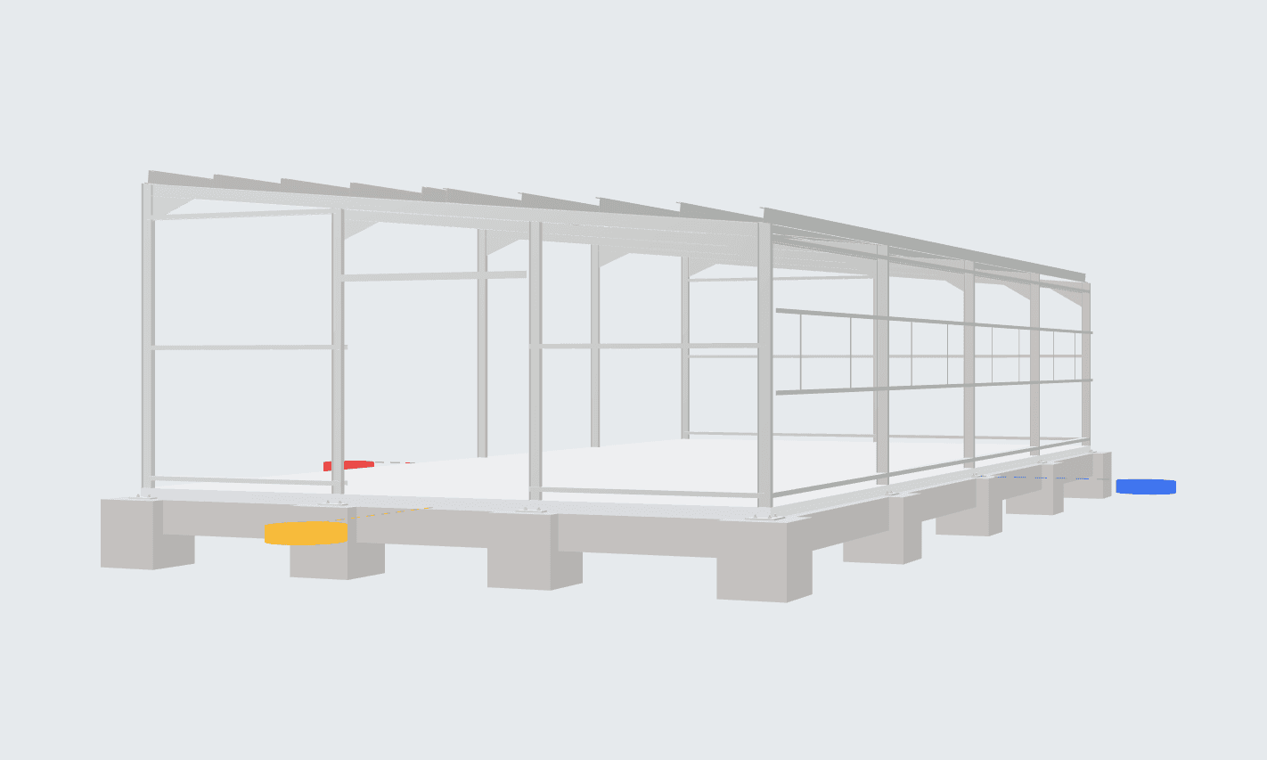
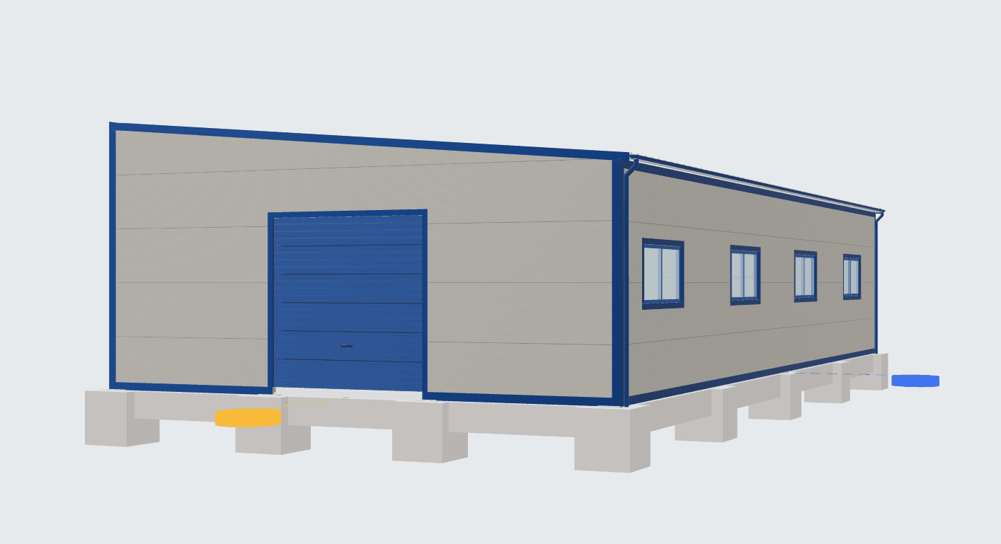
The starting model describes a new part of the hall, not a verified connection to the existing building.
The details describe this starting model. It is a preliminary study, not structural design, fabrication or construction documentation.
Without checking the structure, foundations, fire safety and operation, it is not possible to decide how the connection should be made. The visualisation is only one possible scenario.
What are the actual structure, condition and documentation of the existing building?
Which parts of the operation must remain functional and safe during construction?
How will transport, production, services and fire compartments be connected?
Will the connection require a movement joint, separate foundations or alterations to the cladding?
The Studio opens the 10 × 20 m starting extension. The model helps describe the required new space.
The description is based on the issued template and verified model documentation. Detailed technical assessment belongs to the relevant specialists.
The load-bearing structure consists of five transverse steel frames at five-metre centres. The 200 m² floor area creates new operational space that can be connected to the existing hall in a subsequent design.
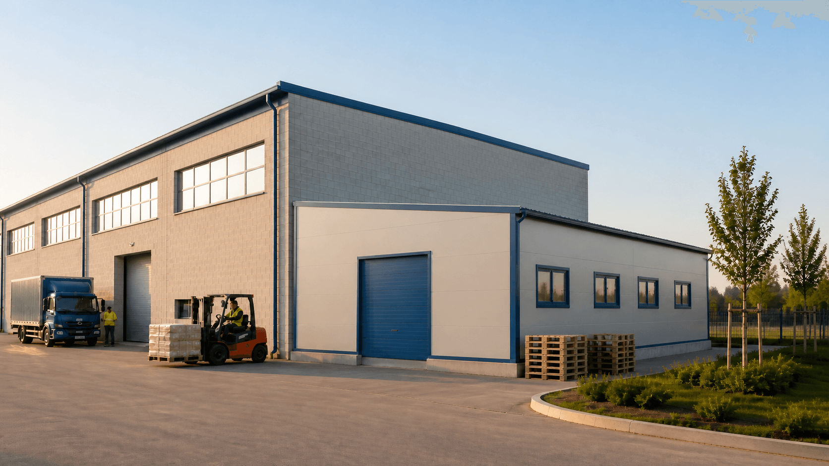
The 5° mono-pitch roof consists of 120 mm insulated sandwich panels in RAL 9006, while the wall cladding consists of 100 mm panels in RAL 9007. The design includes a 3 × 3 m sectional overhead door and four fixed 2 × 1 m plastic translucent panels. This is a study; the connection to the existing building, alterations to its structure, final member sizes, foundations, anchorage and fire-safety design will be determined by the subsequent specialist design. The third image is an AI-generated product visualisation, not a photograph of a completed building.
The study does not define alterations to the existing structure, shared foundations, a movement joint or fire safety. These elements must be determined by a survey and subsequent project design.
The previews help you understand the geometry and scope of the study before opening the model in the Studio.
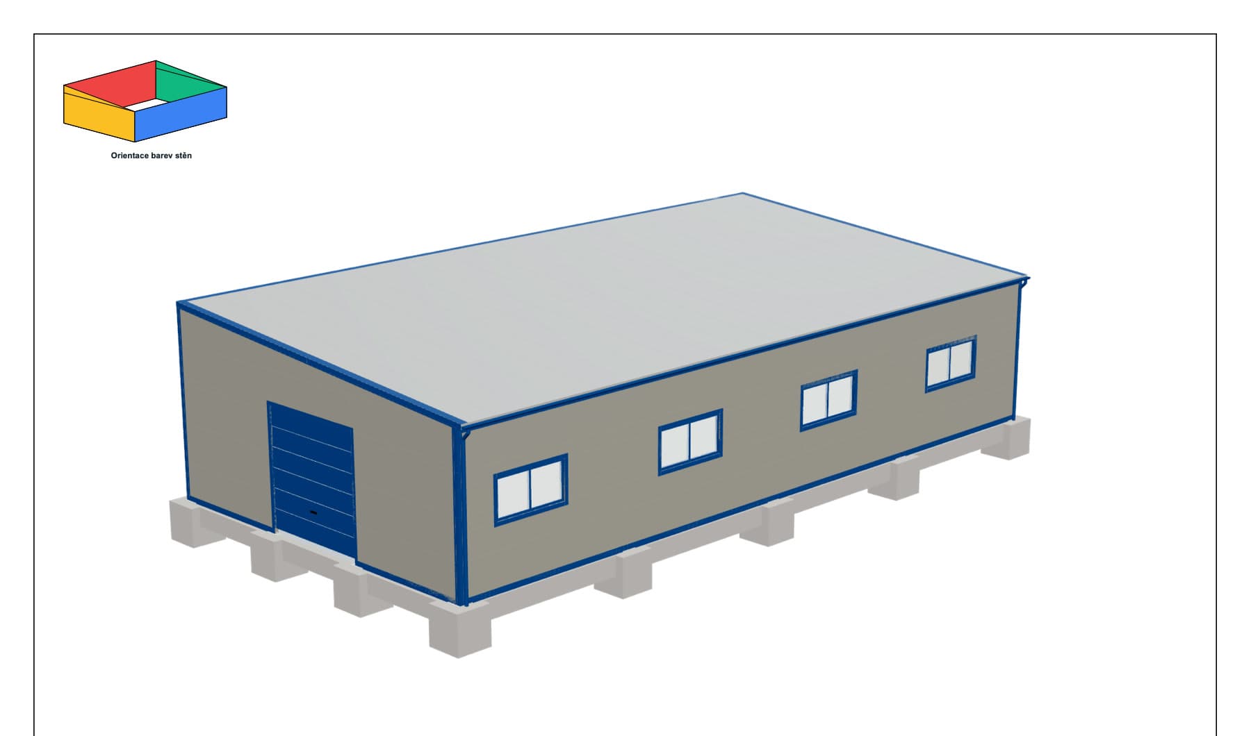
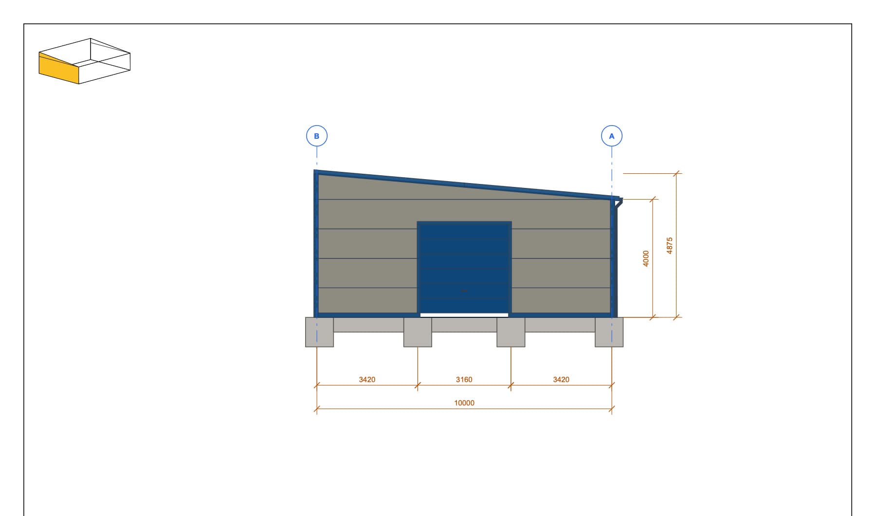
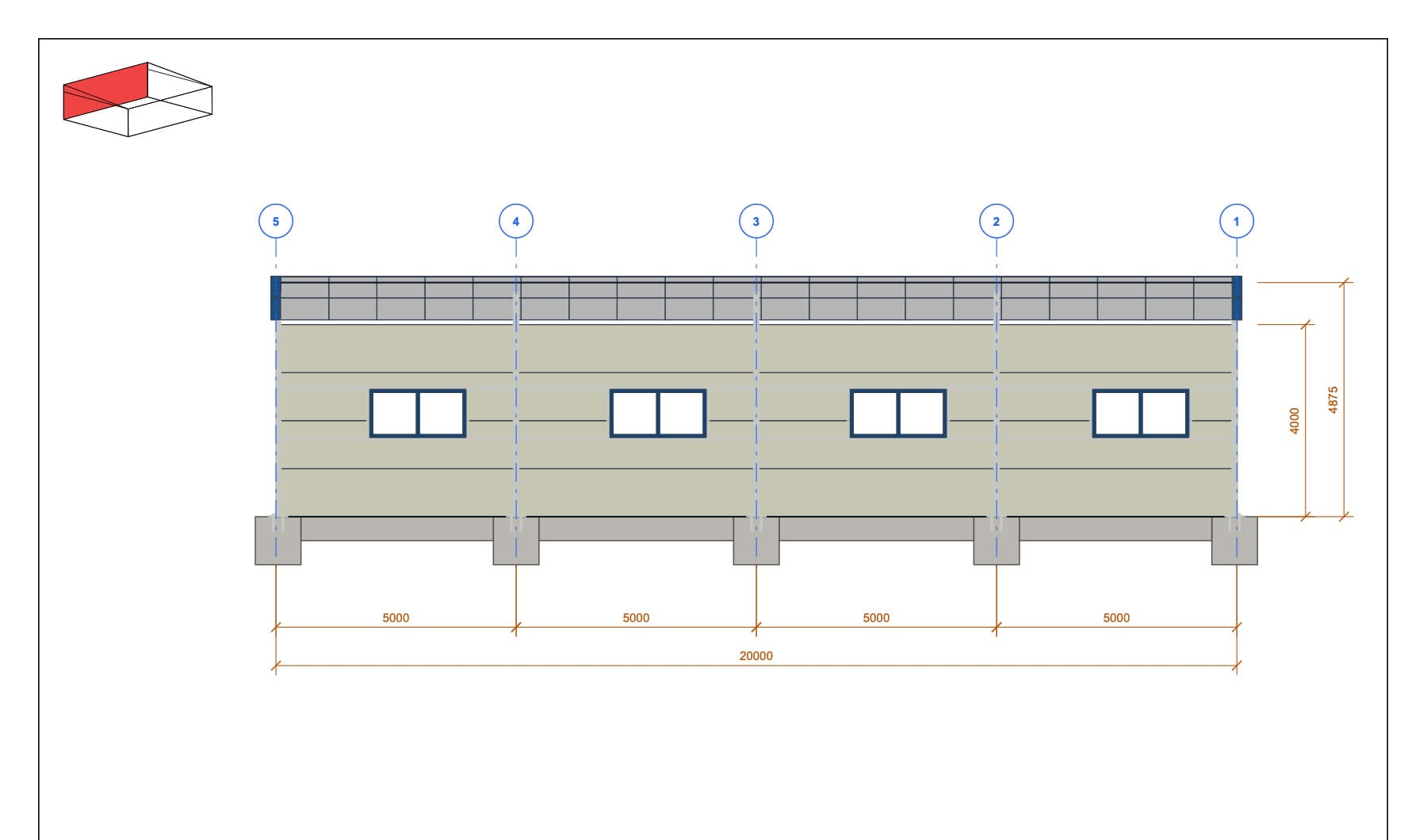
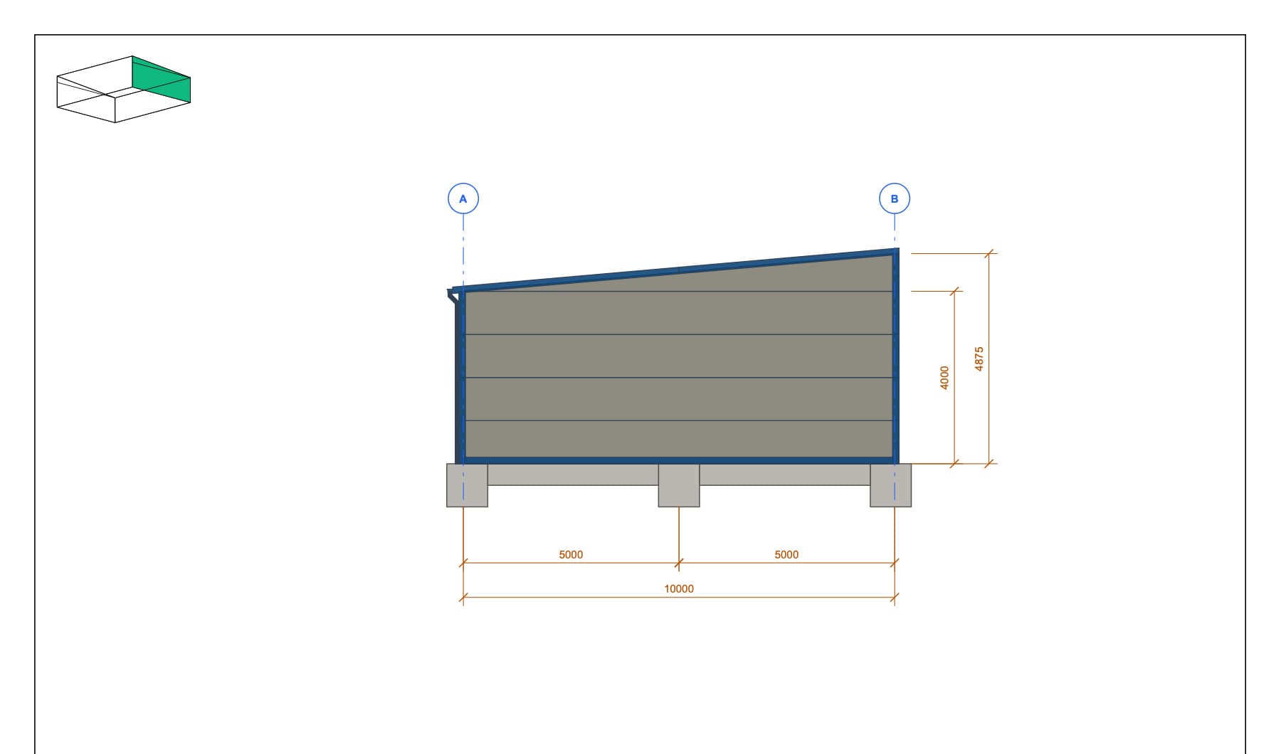
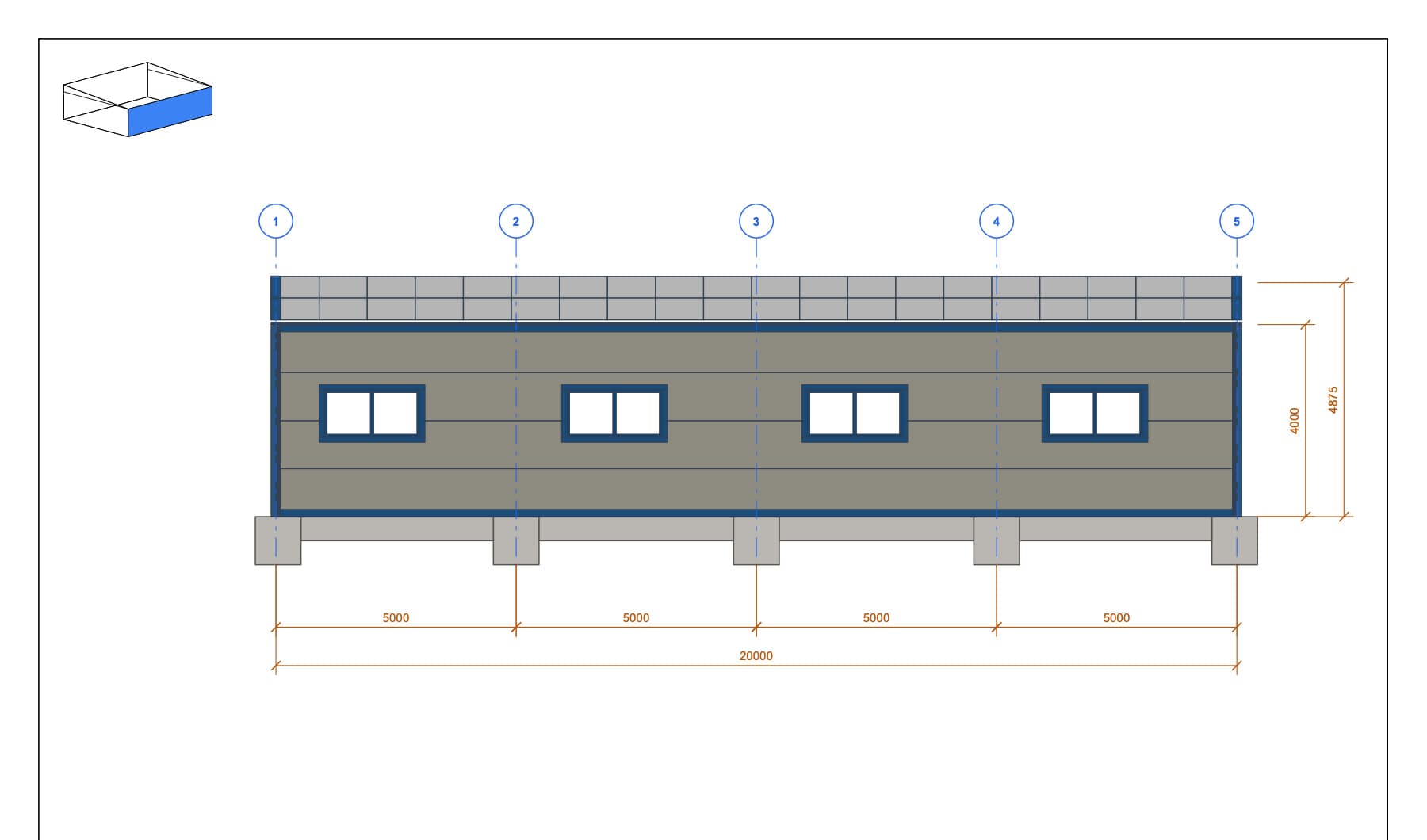
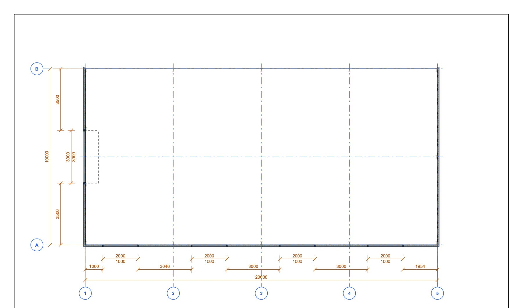
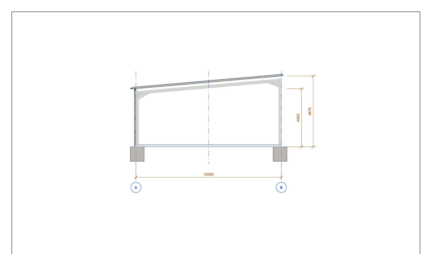
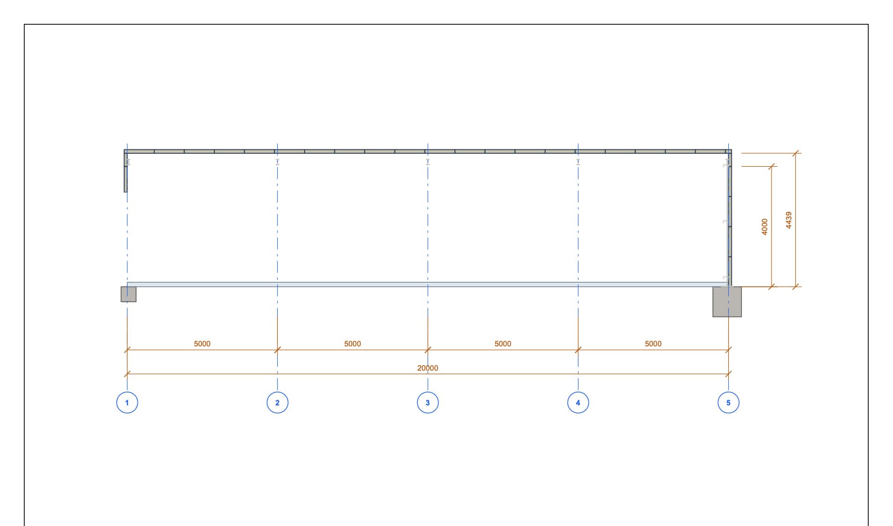
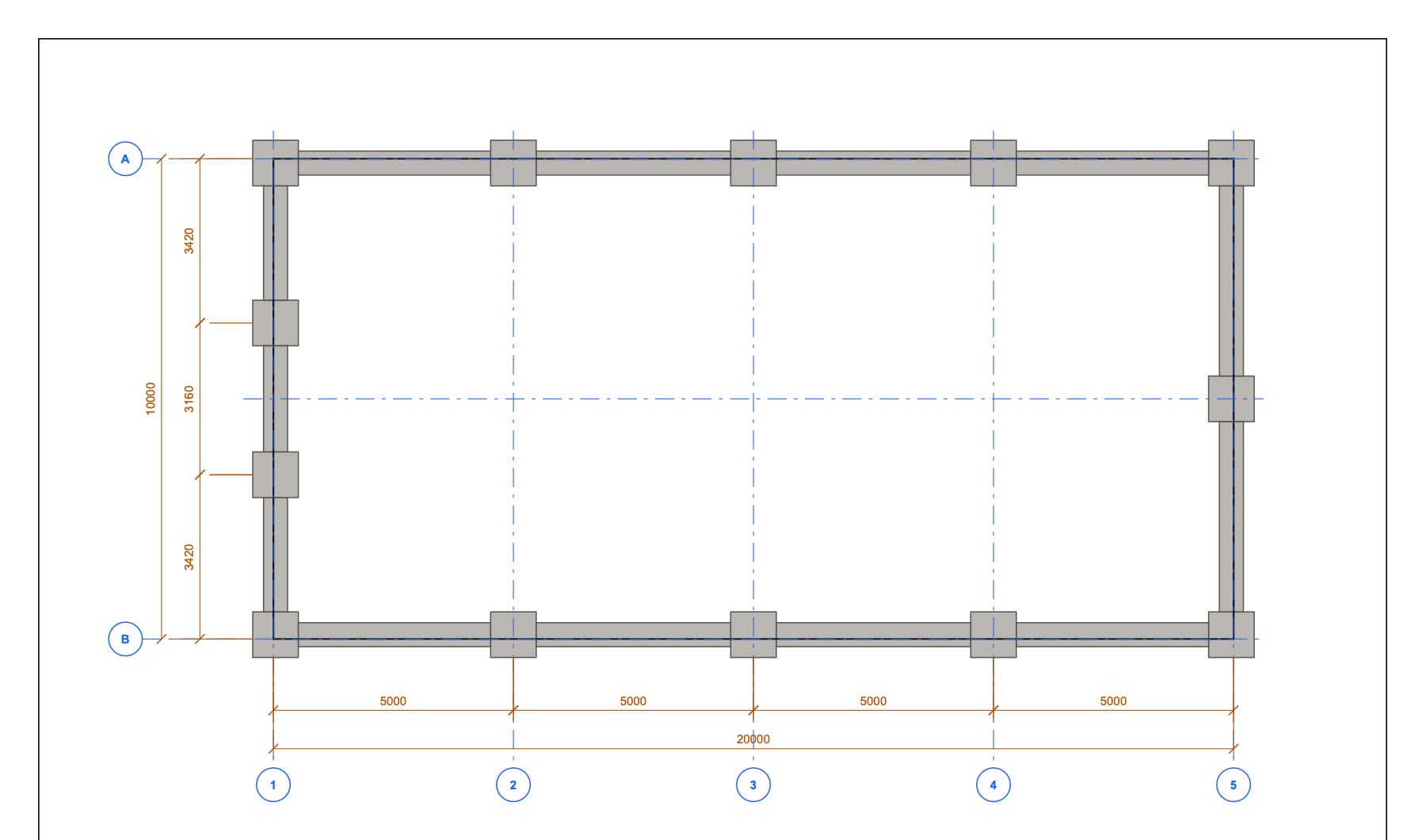
These compact previews show the structure of each file. The labels describe what each document contains.
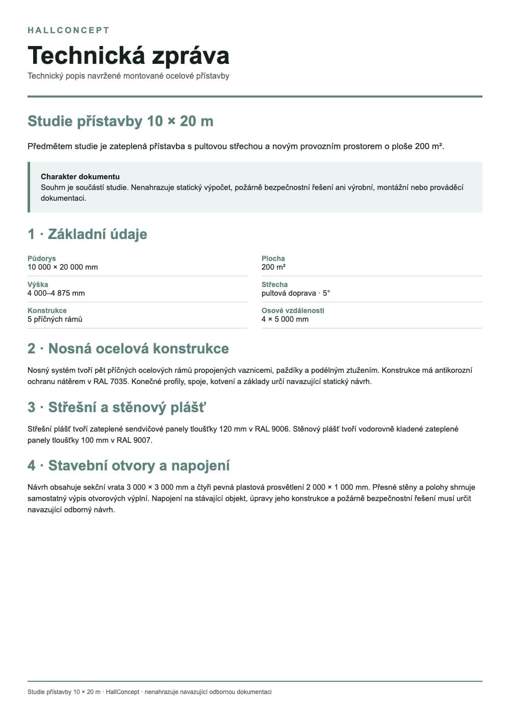 Technical report
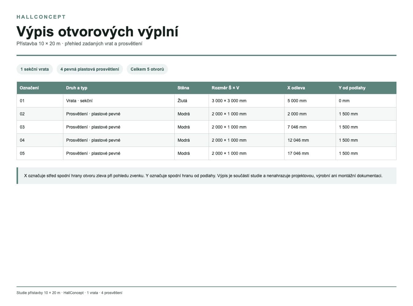 Schedule of openings
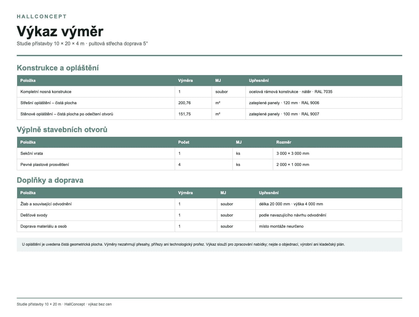 Schedule of quantities
Compare changes to the new part with the site and operational possibilities; the Studio does not technically verify the connection to the existing hall.
Adjust the width, length and height to suit the site and intended operation.
Compare a suitable roof shape and its basic geometry.
Position openings according to the movement of people, vehicles and materials, and the need for daylight.
Try different material and colour solutions for the external and roof cladding.
Answers about the connection, operation and scope of the study.
No. The model shows the new part and a possible visual connection. Actual feasibility must be confirmed by a survey and the designer.
Yes. The documentation and actual condition help determine the structure, foundations, fire-safety implications and safe work procedure.
Sometimes, but a specific phasing plan must be prepared for the separation of the site, transport routes and operational safety.
Open the Studio and adjust the extension dimensions before the connection is assessed by specialists.
Open this model in the Studio